
Online Tutorial.
Wireless X-10 Direct to XTension !
A better antenna for the MR26, W800, and CM15
(and other ideas for improvement)
The silly little antennas that the MR26 and CM15 are born with can be improved. And the W800 can be given a better one. As it is,
typical range from a MS12 motion sensor is less than 30 feet, and often
less than 20 feet.
With a little bit of hacking, it is possible to add on an antenna that can
improve the reception range to over 150 feet.
This should be enough to cover an average size house, if the antenna
is mounted centrally.
Here is the basic idea :
Using only common Radio Shack parts,
most of which can be scavenged
from your junk drawers or an old TV.
The whole thing should cost less than $10,
except that you may have to buy more
of the Twin-Lead wire than you need.
(thanks to Dave Houston for the picture) |
|
 Here is a pictorial of modifying the CM15 ActivehomePRO.
Buy or scrounge the parts
You will need the following items:
- One coil of 300 ohm 'Twin Lead' RS-15-1158 (you need onlly about 40 inches)
- One pre-assembled 75 Ohm Coaxial Antenna Cable (length to suit) RS-15-15321
- One Indoor/Outdoor matching Transformer (BALUN) RS-15-1140B
- One 75 Ohm Chassis-Mount TV Coax Connector RS-278-212 (Pkg of two)
- One "Solder Terminal" with hole large enough to fit around the above connector.
- Wire stripper
- Soldering Iron (15-25 watts is fine)
- Solder (resin-core)
- Wet sponge
- Electric drill
- Drill Bit (3/8 inch)
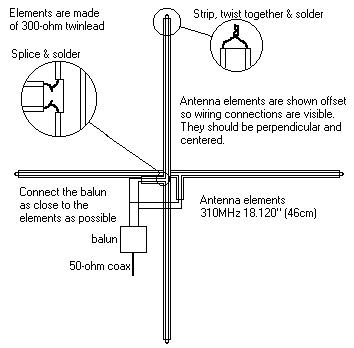
Construct the "Turnstile" antenna
Call it what you want, but it's just two lengths of the 'twin-lead' that are
mounted at right-angles to each other.
- Cut two pieces of the 'twin-lead', each 18 3/4 inches long.
- Strip about 1/4 inch of the insulation from both ends of both pieces.
Do be careful not to 'nick' the copper wires.
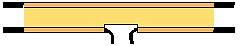
- Mark the Mid-point of each piece. This is important. Make it right.
- Cut ONE of the wires of each piece of twin-lead, exactly at the mid-point.
- Strip the insulation back 1/2 inch on both sides of the cut of each of the wires cut above.
each strip should now look like this:
- TIN each of the stripped wires with solder.
This means simply heat each of the exposed wires and touch a bit of solder to them so that
the wire absorbs a little solder.
- Bend and Solder the two wires at the ends of both strips.
The ends should now look like this :

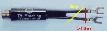
- Cut the wires of the TV matching transformer (Balun) and strip the insulation back
about 1/4 inch :
You really do want to strip more wire on one side than the other, by about the width of the twin-lead...
- TIN each of the stripped wires with solder.
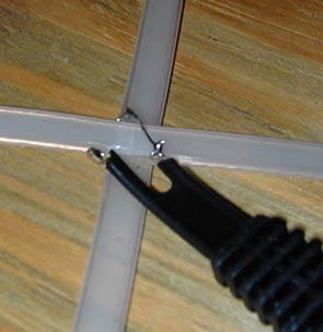
- Place the two strips at right angles to each other, centered at the mid-points.
And position the ends of the Balun wires at a 45 degree angle to the center point.
- Solder the wires...
Notice that the two of the wires of the twin-lead are close to each other, and the other two
are separated. The wire of the balun that was stripped further should extend between the
two separated wires. The other balun wire will neatly sit next to the two twin-lead wires that
are close to each other. (Longer to say than to see. If you've got them positioned correctly,
you'll see what I mean.)
The antenna is now constructed. It only remains to modify the MR26 or CM15 and
find a place to mount the antenna, and connect them together.
Modify the CM15 ActivehomePRO.
Modify the MR26
This part is the most delicate. It is easy, but you do need to take care.
- Disassemble the MR26
There are 3 screws on the underside. One is obvious, but the other two are hidden
beneath two of the rubber 'feet'. The rubber discs can easily be pried out, but be careful
that you they do not 'plink' across the room and get lost. Not really important, but it is
a cosmetic thing...
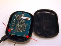
- Pull the plastic bottom off, and discover the circuit board.
Gently pull up on the circuit board at the points indicated by the two red arrows:
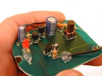
- Turn the circuit board over and notice how the antenna is attached.
You want to be careful that you do not disturb any of the wires connected to the board.
- CUT the antenna wire about 4 inches from the circuit board, and carefully strip
about 1/8 inch of the insulation. (Keep the cut away piece for below)
- TIN the stripped end of the antenna wire.
- Strip and TIN both ends of the cut away part of the old antenna.
You should first cut it to the same length as is the part of the antenna still attached
to the circuit board.
- Locate the hole in the circuit board that is nearest to the point where the
antenna is still attached. This is a very small hole, and may perhaps be covered by the
silicone glue that is holding the antenna wire.
(Note below that I screwed up the first time and cut the antenna wire from the board
without thinking first...
it's really much better to leave that wire alone...)
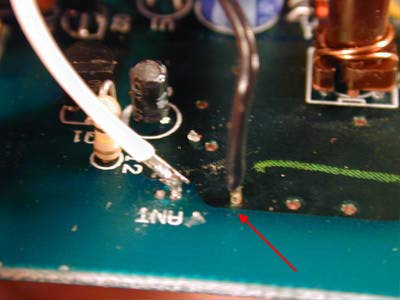
- Insert and Solder one end of the cut piece of the old antenna wire into this hole.
This is probably the most delicate part of this whole operation.
You DO NOT have to put a big blob of solder on this connection.
If you have Tinned the wire before inserting it, and you put just a tiny amount of solder
on the soldering iron tip, then it should take only a 'touch' of the iron and it will be bonded.
DO the soldering from the underside of the board...
- Now it's time to drill the hole...
- Using a 3/8 inch drill bit, Carefully drill a hole in the rear of the MR26 case top.
The plastic is not very brittle, but if you are not careful, you will cause it to split.
Just take your time, and it will be a clean hole.
- Insert the "F" connector into the hole and place the 'solder terminal' on the inside
over the screw base.
- NOW COMES the most frustrating thing about this whole procedure...
- Fit the NUT of the "F" connector onto the screw base, and tighten it.
This is going to be a cause to change your religion...
Just use your 'pinky' to scootch the nut slowly, aligning it, and it WILL eventually bite.
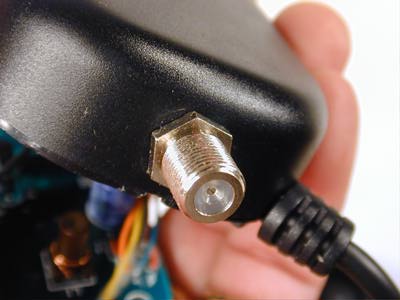
Just before you tighten it with some needle-nosed pliers, make sure that the tab of the
Solder terminal is in the position shown below. (the circuit board ... remember ?)
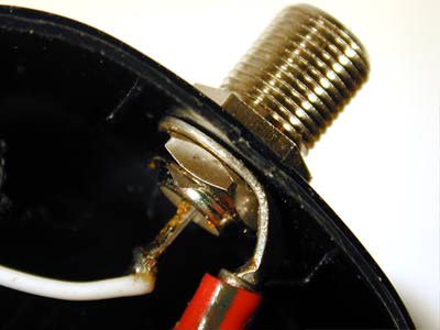
- Almost Finished, Just have to solder the last two wires
- Solder the antenna wire from the 'silicone connection' to the Center
terminal of the rear of the "F" connector.
- Solder the other antenna wire (actually the Ground), to the Solder Terminal
as seen above.
- Carefully tuck the wires back into the top of the case, replace the circuit
board onto the posts, Replace the bottom, re-screw the screws, and replace the
rubber feet.
Now it's time to connect the TV lead-in cable between the MR26 and the Antenna
It's good to do this now, and test the MR26 and XTension before you try to mount it all
in its final location.
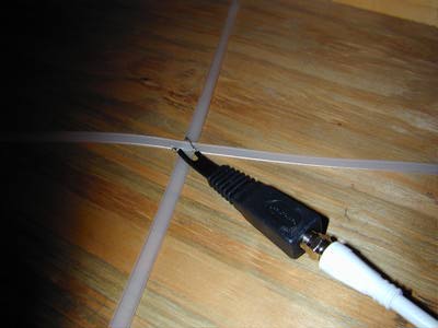
Mounting the Antenna
You're going to want to put the antenna somewhere central to your home, and then
run an appropriate length of the TV lead-in cable between it and the MR26.
But the antenna should (must?) be oriented horizontally.
Maybe on the 'floor' of the attic, or on the ceiling of a central closet...?
I just used some tacks stuck in the plastic insulation of the 'twin-lead'.
Oh, did I mention that now you're going to have to fish that 100 feet of
TV-Coaxial-Antenna-Cable from the attic to wherever you have the MR26 and the XTension Mac ???
A Gallery of Variations
- From Horst Brinker
- From Horst Brinker
Back to the MR26 tutorial
Back to the Tutorials
Home
Copyright 2007, Sand Hill Engineering All rights reserved.

Last modified: February 12, 2005
Michael Ferguson, webmaster(at)shed.com